Pages

Tuesday 8 January 2019

What is more dangerous, A.C. or D.C.?

we are using this term AC and DC for such a long period, How many of us know what exactly AC or DC is? and how did they produce these currents or Voltages?.
The AC or DC is the Currents and Voltages which are used to transmit and conduct electrical energy to the loads, Loads may be either Motor, Light or TV etc….
Electricity: Movement of electrons in a conductor which may be a wire or any conductor is known as electricity.

From the above fig; The Voltage is the driving Force & The Current is due to movement of electrons and finally Resistance which blocks the movement of electrons or current.
Definition of DC:
The DC is known as Direct Current because of it is Constant & flows in one direction( Positive or Negative depends on the source). That’s why the indication of DC is always a Straight Line. Unlike AC; the frequency of DC is zero means it won’t vary with time.
The DC Current which is widely used for charging Batteries; also interestingly whatever power produced from the mother nature is of DC in Nature like Power from Static energy etc.., Also DC power can be stored for the future use; like a backup power.
The efficient way of transmission is DC Power Transmission because of its efficiency. The loss due to harmonics is nil and loss due to inductance or capacitance is very low. But it is recommended only for Long Distance Transmission only because the cost of Conversion DC to AC is very high. So that’s the reason it is not used in shorter distance Transmission.
Definition of AC:
The AC is a Voltage or Current changes its polarity or the direction periodically over time is known as Alternating Current.
AC is known as Alternating Current because the current is not constant, it varies from Positive to Negative for every cycle. The electrons keep on changing its direction forward and backward. That’s how AC current flows. Unlike DC; AC can be used for Shorter Distance PowerTransmission because the loss associated is lesser than DC also it is quite easy to step up or step down the voltages by using Transformers But Transformers won’t work on DC Power. The AC Power can’t be stored like DC because of its alternating nature.
The electrons keep on changing its direction forward and backward. That’s how AC current flows. Unlike DC; Below is the video for How generator works? and How AC produced?.
So Which one is Dangerous?:
AC is More Dangerous because the impedance of Human body is higher for DC and lower for AC, AC which possesses a lethal weapon called Frequency. This will reduce your impedance rate makes you lethal. Frequency increases Impedance Decreases.
Both AC & DC are dangerous it depends on Voltage, duration of contact and Path & the amount of current flow etc..,
Unlike AC; DC current does not change its magnitude, AC will alter its direction for every cycle so the actual AC voltage is denoted in RMS(Root Mean Square). For 120V AC the peak value is 168V So it is very dangerous.
0–5mA – little shock and no damage
around 10mA – Definite Shock and safest current to pull your body parts away or “Let – Go Current”.
More than 25mA – KBoom…Death. u cant Survive.

Thursday 13 December 2018

Charge Controllers PWM Vs MPPT


PWM Vs MPPT

Charge Controllers are the devices which control the input Voltage and current.The applications vary from Solar, Wind or  UPS backup systems etc.These Charge controllers are introduced due to a specific purpose that is to restrict the unwanted spikes in current or voltages to a Battery or other devices so as to protect the Battery from damage.
There are types of Charge Controllers mainly PWM vs MPPT.The PWM(Pulse Width Modulation) is the oldest way of controlling the I-V characteristics and the later is the MPPT(Maximum Power Point Tracking) is the newest addition to improving the battery life.
If the Solar Panel Output cannot be controlled then the battery connected without charge controller will get damage due to uneven output and there is a chance of overcharging that leads to the blasting of battery in extreme cases.
What is PWM Charge Controller?
                                 Related image
PWM refers to Pulse Width Modulation Charge Controller, is a tested and old technology for charging Batteries.The PWM works by matching the battery Voltage by Pulling down the Panel Voltage.
Consider a 100W,12V Solar Panel; At Peak Hour the Solar Panel can produce approx 18V Output Voltage and 5.6A Current Which equals 100.8W.
Consider we have to charge 1 No of 12V & 20AH Battery, then the PWM will bring down the Panel Voltage from 18V to 12V to charge the battery, so 6V is getting Wasted and also the power received by the battery is to be 67.2, not 100W.Thus the efficiency of PWM is Less.
But it is one of the cheap and best charge controller to protect the battery from overcharging.Consider buying Charge Controllers according to your need and Cost for example for cold climates PWM is best suitable than MPPT.
What are MPPT Charge Controllers?

                                    Related image
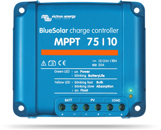
MPPT refers to Maximum Power Point Tracking Charge Controllers which is the new technology developed to increase the efficiency for charging the battery and it works by tracking the maximum power(I-V) at Δt.Unlike PWM the MPPT controller does chop the Voltage but the same proportion of Current will be brought up so as to maintain the output power level.
For Example:
Consider a 100W,12V Solar Panel; At Peak Hour the Solar Panel can produce approx 18V Output Voltage and 5.6A Current Which equals 100.8W.
Consider we have to charge 1 No of 12V & 20AH Battery, then the MPPT will bring down the Panel Voltage from 18V to 12V to charge the battery and also increase the Current level to 8.4A to maintain the power level of 100W.Thus no power loss.

Image result for pwm vs mppt


Thursday 19 October 2017

What is MCB & How it Works?


MCB refers to (Miniature Circuit Breaker) is a device which protects the electrical system from the abnormalities due to overcurrents and protects the load connected to the system.
Now da days various ranges of MCB’s are used from 6A to 16KA in Various domestic, Commercial and Industrial Sectors.Sometimes MCB’s can be called as switches due to the ON/OFF operation, The switching has to be done by manually; under a faulty condition, the switch or the operating lever will trip automatically and after fault cleared the operating lever has to bring normal by manually.


The electromechanical device has 2 arrangements;
1.Thermal
2.Magnetic
The Thermal arrangement of the MCB is to protect from OverTemperature Faults, it has bimetallic strips which in turn actuates the contactor or latch to trip the supply.Generally, bimetallic strips are made from Brass and steel.Under the Faulty condition, the bimetallic strip got heated and bend from one side to other due to the difference in temperature and in turn trip the latch.The MCB while tripping will create arcs in order to suppress the arc the Arc Runner and Arc Splitter employed, below is the illustration.

                    
The Magnetic Arrangement of the MCB works when an overcurrent detected the solenoid get magnetized and in turn trip the latch to protect from the overcurrent.Once the contactor got separated the arc will produce and it will pass to arc runner and finally quenched after arc splitter(arc chutes), The arc chute consists of series of chambers which will cause the arc to split and losses the energy.
The MCB’s are made for different pole ranges from single, double, triple and four pole variants as the application demands.The tripping current capacity of the device also varies for a different application.
Need to Know More? Click the link below;


What is a Diode?

Rectifiers are the device which converts AC(Alternating Current) int0 Direct Current.The conversion requires a device which can perform those operations are called Power Diodes.
                                          
The example of a rectifier is Power Diode which allows current in one direction only from its anode to cathode(forward direction) and blocks in the backward direction due to its semiconductive properties.
Rectifiers are the device which converts AC(Alternating Current) int0 Direct Current.The conversion requires a device which can perform those operations are called Power Diodes.
The example of a rectifier is Power Diode which allows current in one direction only from its anode to cathode(forward direction) and blocks in the backward direction due to its semiconductive properties.

The Diode is made of Silicon or Germanium; P and N-type were made by adding impurities to the silicon which will be either trivalent or Pentavalent element.
The Process of adding impurities to the semiconductor is known as Dopping.
If the applied voltage more than the barrier voltage of the Diode then the diode will conduct in the backward direction also.
From the above Fig, we can see that the battery Positive is connected to the  Anode and Negative is connected to the Cathode, The P side of the Diode is rich in holes and deficit in electrons Vice versa for N Side. Before applying any voltage Depletion layer will form between P and N Sides due to Thermal excitation.
UnBiased Condition:
Before applying any voltage Depletion layer will form between P and N Sides due to Thermal excitation.The thermal excitation influence the holes movement from P side to the N side and electrons movement from N side to P side.The holes will recombine with the electrons in the N side and the electrons will combine with the holes in the P side this effect creates an immovable region in which all the movement of electrons and holes are seized.This process is called diffusion. The P side will have immovable -ion and N side will have +ve immovable ion which causes static electric field in the depletion region.
                                        
Forward Biased Condition:

When the Diode is forward biased; the Positive end of the battery connected to the P side( Anode) and the Negative terminal of the battery connected to the N side of the diode(cathode), is the movement of electrons, causes the flow of current in the diode but there is a depletion region in the diode(P-N Junction) where there are no any free electrons but when we apply an external voltage then the voltage is higher than the barrier voltage the diode will conduct.
The Barrier Voltage of the Silicon Semiconductor is 0.7V and for Germanium is 0.3V,  Assume the Voltage of the external Source is 0V; Unless until the forward Voltage to the diode reaches 0.7V the diode won’t conduct any current.When the Forward Voltage of the diode is more than the barrier voltage then only the diode will start conducting current.The time taken to overcome the barrier voltage of the diode is known as the Recovery Time.
Reverse Biased Condition:
When the Diode is Reverse Biased; Positive terminal of the battery or source is connected to the cathode or N side of the diode and the Negative terminal of the Battery is connected to the P-Side of the Diode or Anode then the Depletion Zone become much wider that no current will flow, but actually a small amount of current will still flow from N type to P type that’s due to the minority charge carriers.


 The Diodes maximum reverse biased voltage without breakdown is known as Peak Inverse Voltage (PIV), if we keep on increasing the reverse voltage then at one stage the depletion region will be destroyed due to the flow of huge reverse current; the Diode also will get destroyed permanently.This breakdown is known as Avalanche Breakdown.The PIV is linked with the temperature also as Temperature increases the PIV increases and vice versa.
Avalanche BreakDown: When the applied reverse voltage is higher than the breakdown voltage than the depletion region will get destroyed then due to higher potential the free electrons get energised with kinetic energy kicks the atoms of the device to accumulate more electrons by breaking the covalent bonds, thus the accumulation of huge electrons causes the flow of huge current then the Diode will get destroyed eventually.

Thursday 4 August 2016

RCCB Vs ELCB


RCCB refers to Residual Current Circuit Breaker which is a rival to the ELCB(Earth Leakage Circuit Breaker). As both the circuit breaker works for the same cause but the difference is RCCB connectivity is different also it gives better protection over ELCB.

ELCB is a voltage operated device which has Line,Neutral, and Earth Connections detects potential in the earth when the voltage is non-zero and indicates that there should be a leakage current in the earth and it protects by tripping.The ELCB can protect from earth fault only  and doesn't provide protection from overload and short circuit so better opt for RCCB than ELCB.


Meanwhile, RCCB which has Line and Neutral connections and the working is when there is a difference in current level from Line to neutral indicates a fault or earth leakage and it trips.As line current always equal to the neutral current which flows back in neutral conductor any difference in current means that somewhere earth fault occurs so the RCCB will get tripped.

The RCCB doesn't require earth connection so that even it can provide shock or fault protection to the device which does not have the earth of its own.

The Tripping of the RCCB is within 30milliSeconds of the earth fault.
The widely used RCCB rating is 30mA and 100mA.
The Human body can withstand up to 30mA.

Like ELCB, RCCB doesn't protect from the following,

1.Overload(Due to huge current even undetected).
2.Nuisance Tripping(Due to sudden changes in electrical load like switching Airconditioner or Motor etc...)
3.Non-Standard Waveforms(Not guaranteed for the operation by other than nominal waveforms like from halfwave rectifiers).
4.Short Circuits(Due to Line-Neutral Schock).

Thursday 11 February 2016

Lithium ion batteries


Lithium ion battery,aviation battery,LI-Ion battery,battery,telecom battery


Lithium ion batteries,These batteries are now becoming popular especially in telecom sectors,Space projects etc...because of their charging and discharging feature,Compact,energy density and finally the monitoring feature involved in Li-Ion batteries.

Working of a Battery?

The battery is a storage device that converts Chemical Energy to Elecrical Energy.These batteries are having 3 major parts or components which are Anode(negatively charged),Cathode(Positively charged) and Electrolytes.

For example,Take one container and fill it with diluted sulfuric acid as a electrolyte. Now immerse zinc and one copper rod in the solution and connect them externally by an electric load.This is called voltaic cell, Current will start flowing through the external load.

Zinc in diluted sulfuric acid gives up electrons as below:

Zn ----->Zn++  + 2e-
                                               
These Zn + + ions pass into the electrolyte, and their concentration is very high near the zinc electrode. As a result of the above oxidation reaction, the zinc electrode is left negatively charged and hence acts as cathode. The diluted sulfuric acid and water disassociate into hydronium ions as given below:

H2SO4 + 2H2O -------> 2H3O+  + SO4-

                                     
Due to the high concentration of Zn + + ions near the cathode, the H3O+ ions are repelled towards the copper electrode and get discharged by removing electrons from the copper atoms. The following reaction takes place at the anode:

2H3O+ + 2e-  ----------> 2H2O + H2

                                     
As a result of the reduction reaction taking place at copper electrode, copper is left positively charged and hence it acts as the anode.


Lithium ion battery,aviation battery,LI-Ion battery,battery,telecom battery,working of battery


Lithium ion Battery?

These batteries having better features compared to other lead acid or other batteries because there will be a monitoring section provided which can give you all real time data's at that time, means Voltage of individual cells,battery pack,total voltage,cell temperature,Over current or Under current etc...., each and every parameters of the battery including SOH and SOC also tracked using the in-build BMS(Battery Monitoring System).


The Lithium ion batteries have high energy density, means the amount of energy stored per unit volume is higher than the traditional Lead acid batteries so that the size of the battery was compact too.

The Li-Ion is a lightweight metal so that it is easy to form ions at the time of chemical reaction,The Li-ion battery can store as much as twice of the power Lead Acid battery can hold and also these batteries are also environmentally friendly but susceptible to 100% discharge so 80% discharge is recommended.

Let us take an example of 48V/75AH Li-Ion battery,so it has 15 no of 3.2V cells connected in series,thus makes you 48V battery.thus for the same size it give twice the power of other battery types.

These batteries have some modern electronics involved to better understand each and every parameters,so mainly BMS (Battery monitoring system),Contractors,Temperature sensors,Shunt,RS485,Data Logger,CAN.

The BMS may contain MOSFET to replace contractors which are responsible for charging and discharging,The BMS can able to control the battery from fail due to any Over or Under current/Voltage/Temperature,also it has alarms in case of any problems occurred so that these BMS are very helpful to protect batteries by monitoring all possible parameters.


RS485 which is used to monitor the parameters by connecting PC/Laptop.CAN communication is used to communicate between each battery so that the data logger can store the data of all the batteries.Data logger is used to log all the parameters of the battery and generally the Master module hold data logger and CAN communication allow to get information from each battery.


Lithium ion battery,aviation battery,LI-Ion battery,battery,telecom battery,working of battery
The commercially used negative electrode is graphite and  positive electrode will be one of these three materials- lithium cobalt oxide, a polyanion-such as lithium iron phosphate or a spinel -such as lithium manganese oxide.The electrolyte will be a mixture of some organic carbonates such as ethyliene carbonate or diethyl carbonate containing complexes of Li ions,

Charging:

The external voltage was given through any external charger with the same polarity is applied between the electrodes, thus the charging process will start. The lithium atoms leave the metal oxide structure and ionize into Li+ ions under the release of an electron of each one. In this process Li+ ions diffuse to the negative electrode(anode). At the surface of the graphite particles the Li+ ions and electrons recombine with each other forming neutral lithium atoms and are reintercalated into the molecular structure of the graphite particles,otherwise Lithium is deposited in the anode.When no more ions will flow, the battery is fully charged and ready to use.

Ref:TUM EES YouTube Channel

Discharging

During discharge, lithium atoms oxidize by forming Li+ ions and electrons, whereas Li+ ions move to the positive electrode diffusing through the electrolyte and the separator. The electrons flow from the negative electrode to the positive on the external circuitry, where the resulting current flow can be used for an application. At the positive electrode the electrons recombine with the Li+ ions and are stored in the molecular structure of the active material, otherwise Lithium is deposited in the cathode.When all the ions have moved back, the battery is fully discharged and needs charge again.


Friday 27 February 2015

Inverter/Offline UPS and Online UPS

Any person will tell you that both the inverter and the UPS are used to give your electrical and electronic appliances and gadgets a backup power support when there is an electricity failure in your office or home.

 A layman will also tells you that the electricity backup from the UPS is instant and it does not let your electronic gadgets to get switched off and the electric supply is continuous and that is why it is given a name UPS which stands for uninterrupted power supply. 

However, the backup supply of power from an inverter gets delayed by one or two seconds, which causes your electronic gadgets to get switched off and you have to switch them on to start them again. This is the reason that most people use UPS to support backup of electricity to their computers and other costly electronic equipment, which otherwise get damaged due to sudden power failure. 

inverter vs ups,offline ups,online ups,inverter,solar inverter,solar,solar power,difference between inverter and UPS,UPS,uninterruptable power supply

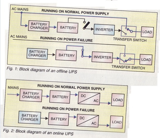
Fig.1&2 shows the block diagram of a INVERTER vs UPS.

Let us now define the difference between an inverter and a UPS from the technical point of view:

UPS: The one power cable of your UPS is fixed in the power socket of your wall when the power is on. So, the UPS keeps on getting a regular power supply from the mains when the power is on. This AC power received from the mains power source continuously keeps on being converted to DC. This DC power keeps on charging the battery of the UPS in a continuous charging mode. 

So, the battery of the UPS is always kept charged during the time when the power is there in the mains. The output from the battery goes to the Sine wave inverter of the UPS. It converts DC to AC and this feeds the equipment. This makes it very clear that the power to your electrical gadget which is connected to the UPS is always supplied from the battery. 

Due to the power always being drawn from the battery to the electrical equipment, there is no time lag in case of electricity failure and the flow of the mains power stops. It is only the battery of the UPS which stops from being charged since there is no power in the mains. However, the backup power from the battery of the UPS keeps on being supplied uninterrupted till the battery is discharged and is no more able to supply the power to the eqauipment. 

This is why we find that the backup power of the battery of the UPS is of very short period ranging from 15 – 20 minutes upward. The more is this backup time of the UPS battery, the more will be the cost of the UPS. Otherwise also, the circuitry of the UPS is expensive making the UPS even of a small backup time more costly. 

Inverter: As far as the power to the inverter is concerned, like UPS it also comes from the mains for the inverter battery to get charged when there is no power cut off. The main difference between the inverter and the UPS lies in the fact, that in an inverter, the power is directly sent to the output which is connected by wiring to various appliances. 

At the same time the AC is also converted to DC and this DC is constantly charging the battery. On the other hand, the power to the appliances is not directly sent to the output but it goes from the battery of the UPS which keeps on getting discharged. A sensor and relay mechanism checks whether the mains is ON or OFF in an inverter. When the mains get switched off, the relay mechanism triggers to switch from mains to inverter. Rest is same like the UPS. Because of this sensor and relay, there is a gap between triggering.

Ads Inside Post

Share English German French Arabic Chinese Simplified